Isolated Airfoil
Shape Optimization
Positioning of the
slat & flap of a
3-element airfoil
Optimal Airfoil
Shapes at different
operating conditions
Combined Cycle
Power Plant
Optimization
Optimization of Combined Cycle GT Power Plants
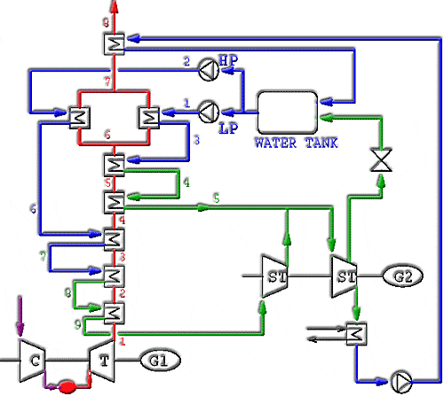
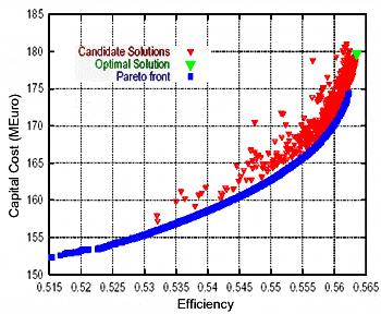
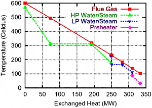
The targets are to reduce the capital cost and to increase the efficiency of the natural gas fired, dual-pressure CCGTPP configuration shown below:
 |
GT: 260 MWe, 38% efficiency, exhaust gas mass flow 615 kg/sec at 600C.
The design variables are:
- HP steam pressure
- LP steam pressure
- Superheated HP steam temperature
- Feedwater temperature at the inlet to the HP evaporator
- Feedwater temperature at the outlet from the first HP economizer
- Ffeedwater temperature at the inlet to the LP evaporator
- Ssuperheated LP steam temperature
- Ssteam pressure fed to the water tank
- Exhaust gas mass flow ratio (percentage of mass flowrate traversing the LP economizer)
- Exhaust gas temperature at the HRSG outlet
- Steam extraction pressure from the LP steam turbine
- Exhaust gas temperature at the inlet to the condensate preheater
 |
 |
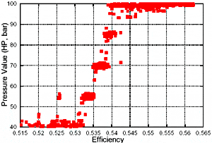
HP Pressure Values, over the Pareto Front |
